
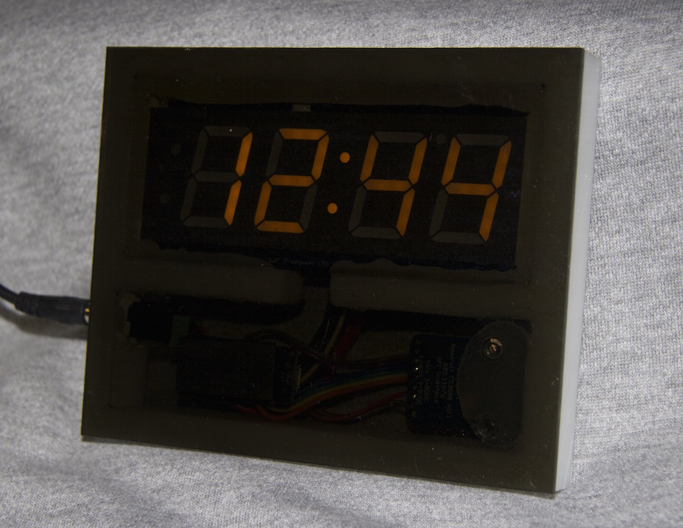
Finished Smart Clock.
While not a planned event, I typically end up working on some electronics project near the end of the year. This year, the stimulus was the end of daylight savings time. With twelve clocks in the house, it ticks me off that I have to manually reset each of them twice a year. Not really all that much, but enough this time to replace my old radio clock with the wrong daylight savings program – yea, it’s that old.
The Brains
I have used various micro controllers in the past such as PICs, BASIC Stamps, Rabbit Semiconductor boards and Raspberry Pis, but the current model that would do the job is the Arduino Uno R3.
Arduino is an open-source electronics platform based on easy-to-use hardware and software. It’s intended for anyone making interactive projects.
The platform has a great, open-source programming interface and there are plenty of code samples and HowTos online.
7-segment Displays Made Easy
The first hurdle to building a clock was the display. I needed a 4-digit, 7-segment display and I wanted it big. I’ve also never worked with one and figuring out the program for managing fourteen wires was not something I was looking forward to. Fortunately, I found the Adafruit 1.2″ 4-digit 7-segment display w/I2C backpack which is just frickin’ awesome! The backpack includes the driver chip necessary to multiplex the display and it only requires 4 wires to run it using an I-squared-C bus. Additionally, these displays are very bright!
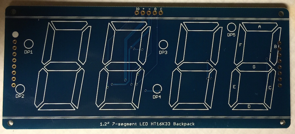
Adafruit 4-digit, 7-segment I2C backpack.
Display assembly was pretty simple. I matched up the pins on display with the printing on the backpack, soldered the pins, wired the backpack to the Arduino and wrote some code. It took about five minutes to attach the display to the backpack which included heating up the soldering iron. This backpack actually has five wires that connect to the Arduino, but two of them are +5V so I tied them together in final assembly.
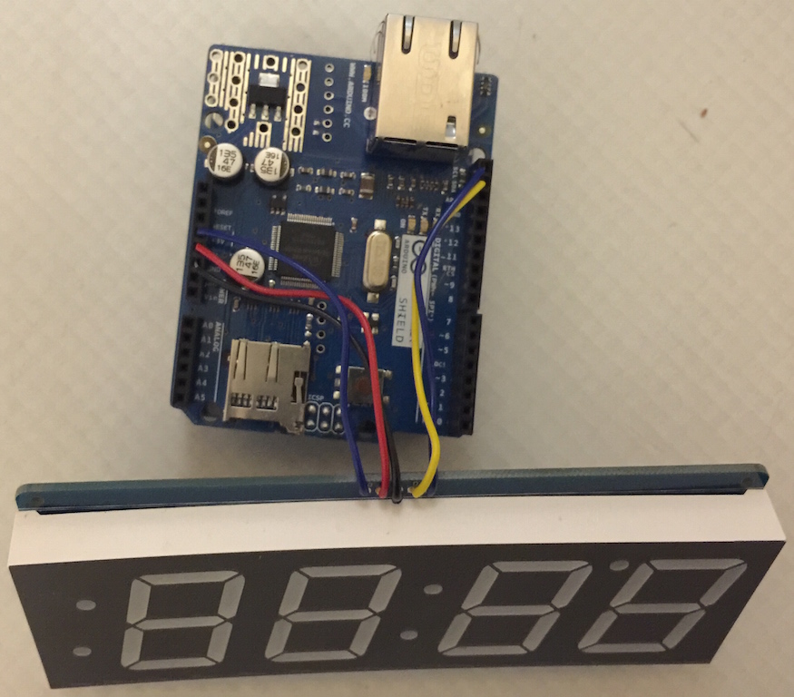
Arduino Uno w/Ethernet Shield and 7-segment display.
Adafruit provides an Arduino library for driving the display that includes code examples for sending numbers to the display which made that part very easy. One of the capabilities I noticed while looking at the library code was the ability to control the display’s brightness. I created a routine that sets the brightness based on the hour. I set it for maximum brightness at noon and minimum at midnight varying in between. This is a cool feature because you can see it easily during the day when the sun is bright, but it doesn’t keep you awake at night by lighting up the room. Run it at full brightness if you need a night light.
Networking
My Arduino board does not include native networking support so early prototypes of the project used an Ethernet Shield shown above that adds a wired ethernet connection. The Arduino development environment includes code samples for communicating with an NTP server to retrieve the current time. While very cool, NTP would not work for this because there is no automatic support for daylight savings. Additionally, connecting an ethernet cable to the clock was fine during prototyping, but I wanted WiFi for the finished product.
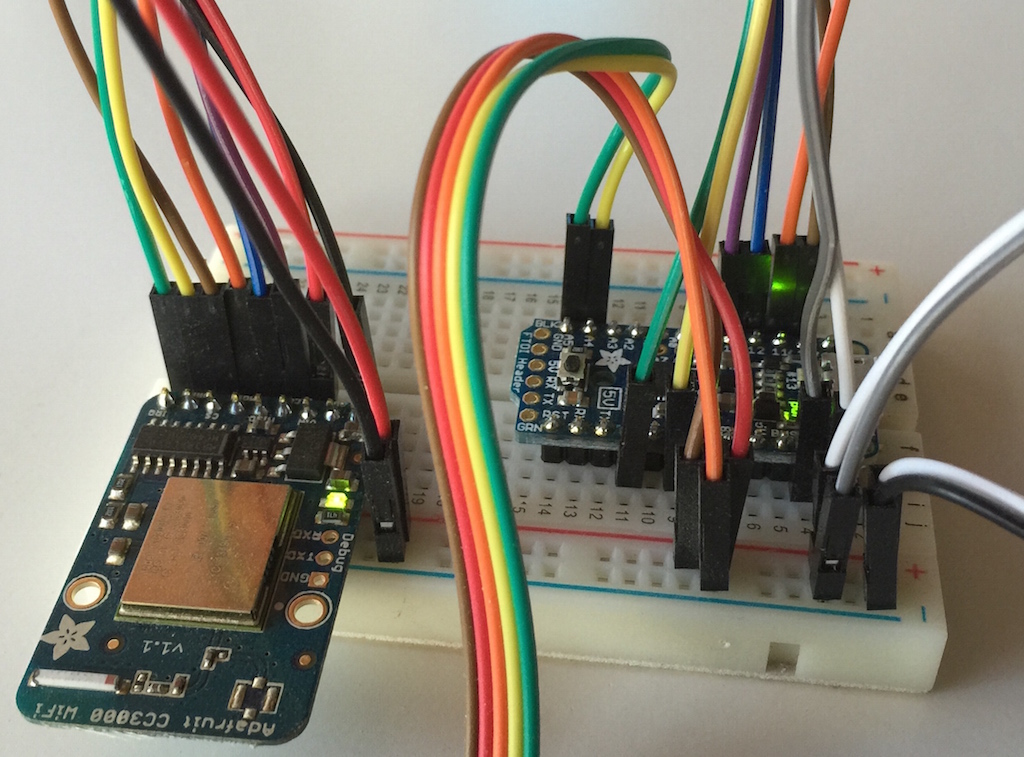
The breadboard stage includes WiFi and an Adafruit Trinket Pro.
Adafruit has a WiFi breakout module that can be used with virtually any micro controller. It requires eight wires including power and they have an Arduino library for the board. While support exists for choosing the WiFi settings remotely with a mobile phone, I took the short-cut and hard-coded the settings in the code.
At this point, I’ve converted the micro controller to an Adafruit Trinket Pro 5V, essentially a smaller version of the Uno (same chip) with a few missing features. Since the missing features aren’t needed for the finished product, it really is a nice solution.
Getting the Current (Local) Time
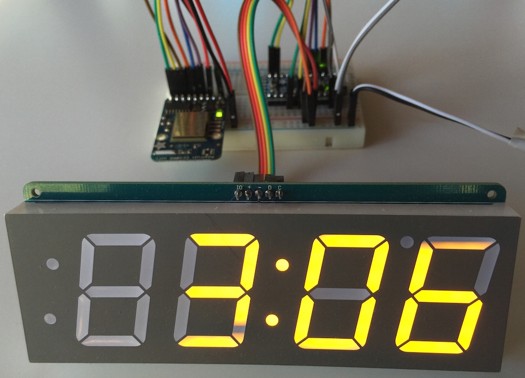
Working breadboard prototype.
I have a linux box running an Apache HTTP server with PHP. I created a page that returns the current local time in a string such as {{2014-12-11T11:06:41-0600}}.
I used the moustache template format in the return string which allows for a smaller receive buffer on the Arduino. When the web call returns, the content is parsed as it’s read. Buffering only the part between the moustaches is easy. This saves precious memory since the HTTP headers are part of the response and would be included in full-page buffering.
The Arduino checks the time at 1:01am, 2:01am and 3:01am every day to check if the RTC needs to be reset. When a daylight savings change occurs, the time will be off by an hour for one minute which is fine for my needs.
Final Assembly

Finished project from the back showing components.
I looked into casting acrylic to make an enclosure, but that seemed to be way too difficult to get right and would have required more time than I wanted to spend. I ended up buying some scrap pieces from Austin Plastics & Supply. I found a piece of half-inch thick solid white acrylic to house the electronics and display plus a thin sheet of smoke tint for the front.
The most expensive part of this project was the ten-inch, eighty-tooth high density carbide blade for my table saw. It cut through that half-inch acrylic like butter and the cut was very clean with no finishing needed. Totally worth it! I cut the center out using a recently-acquired scroll saw. The cuts are not precise, but good enough to make everything fit. I used white silicone to hold the display in place (and prevent any stray light from shining through) and velcro to hold the Trinket, the RTC and the WiFi module.
You Really Need a Clock
While exploring the enclosure options, I ran the project in it’s breadboard state shown above for a couple of weeks. I noticed that the time was wrong on a couple of occasions, but it would correct itself within an hour when checking in with the linux server.
The Arduino has an internal clock, but it’s really just a millisecond register that eventually rolls over to zero. While not a problem for the internal timing needs of the Arduino, it’s not accurate enough for a clock. Adding an RTC (Real Time Clock) circuit to the project solved the problem and even allowed me to reduce the calls to the server to thrice daily versus once an hour. I attached the RTC module to the display’s backpack with velcro. It is the tiny board to the right of the wiring. The RTC’s backup battery is supposed to last five years. I’ll let you know.

Front view of the final assembly.
Final Thoughts
The only thing I’d change in the design is to make the case a little wider to allow better centering of the display. It isn’t that noticeable in the dark, but the numbers are noticeably off to the right a little during the day.
This was a fun project and I’m ready to toss the old radio clock out. The down side is that now I want to replace more clocks.